15 Transistor Equalizer Circuit Diagram Robhosking Diagram
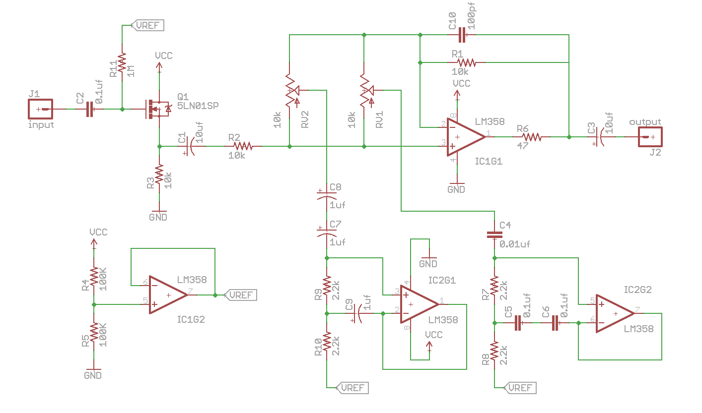
Here is a circuit diagram of a simple to build graphic EQ. Notice that the circuit is very repetitious. the frequency selective elements are made of capacitors and "gyrators" that simulate the response of grounded inductors. These make the circuit free of real inductors, and are simpler to tune if tuning is needed.. A commercial guitar.

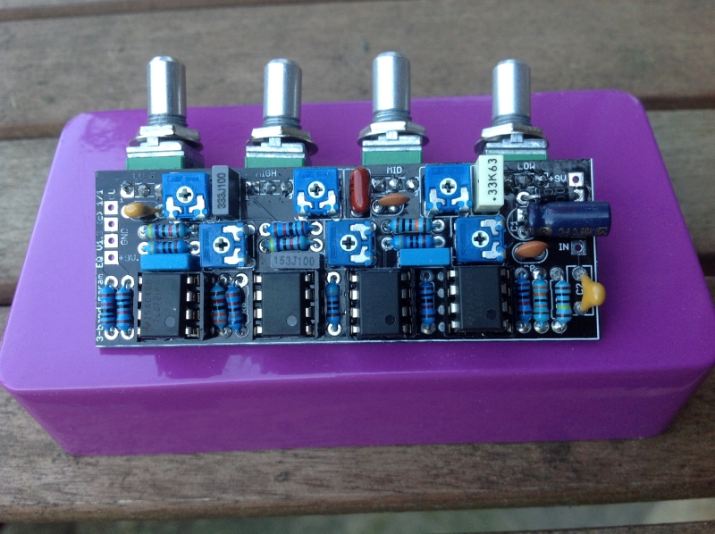
3 Band Equalizer
Room Resonances. If you recorded the acoustic guitar at home, in a less than ideal recording environment, you should next eliminate unwanted room noise. Go to your EQ plugin, boost the band up to 12db then set the Q to 5. Drag the band around the frequency range and listen for distracting room sounds e.g. an air conditioner or road noise.
Equalizers DIY TH custom effects
The EQ for most acoustic guitars should prioritize enhancing the natural resonance that the acoustic guitar's body provides, as well as the presence of the strings over the soundhole. Below are a few basic guidelines for acoustic guitar EQ. Lows (0 - 200HZ) - Acoustic guitars generally don't have much frequency response below 200 Hz.

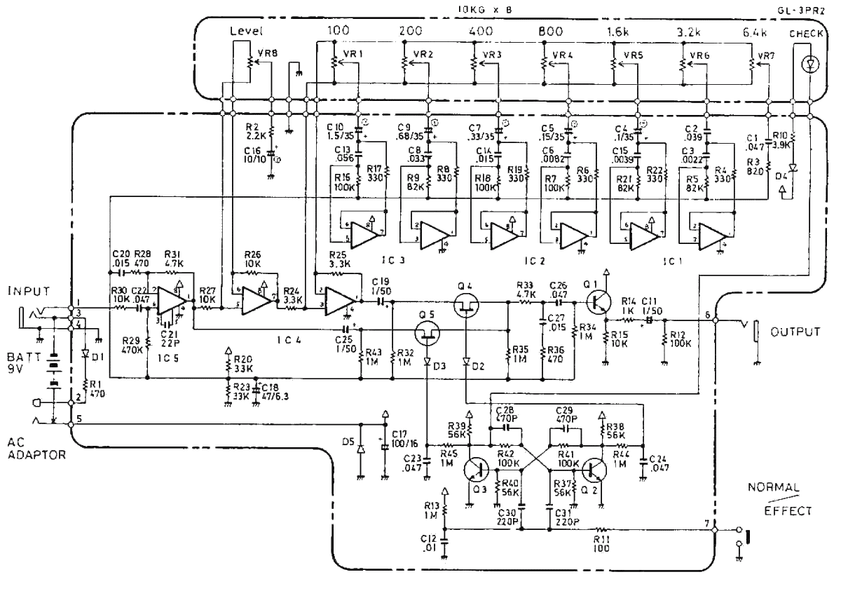
5 BAND EQUALIZER CIRCUIT USING TRANSISTOR in 2020 Equalizer, Circuit, Transistors
Dealing with guitar at every stage of the process, from stage to recording to mixing, has given me a broad perspective of EQ. I thought I would share some of my findings on the subject of guitar EQ—one thing to remember about getting a tone that it's merely an audio opinion. There are many ways you can approach sound.
Parametric Equalizer Schematic Diagram IOT Wiring Diagram
A guitarist's guide to EQ: how to make your guitar tone bigger and better than ever before By Alex Lynham published 29 April 2020 Whether you're playing live to thousands or creating mixes in your bedroom, EQ is an essential but elusive tool. We break it down for you in this comprehensive guide (Image credit: Future) Jump To:

Equalizer Performance Guitar
A well-designed inductor-based equalizer can provide incredibly musical boosts and cuts and can include bandwidth controls to create shelving, bell or parametric filters. Coloration from MakeUp Gain Once our signal has been tone-shaped, we need to boost the signal back up to its original level; so passive equalizers include makeup gain amplifiers.

3 Band Audio Equalizer Circuit
For a while I've wanted to experiment with making a very basic passive EQ circuit - the simpler the better. (I'm virtually an electronics novice. meaning - I can connect a battery to a bulb with a variable resister wired in series, that's about the extent of my electronics 'genius') Two concerns: 1. I don't know where to start - a Google search pulls up hundreds of schematics.
Diy parametric equalizer / /free graphic equalizer circuits/
Here's my first attempt at a parametric equalizer. I combined parts of the graphic equalizer I did previously with information on how to make gyrators from R.G.Keen at Geofex. There's a schematic and a vero layout, and I haven't verified either yet. Updates to come soon. Update (13.01.2011): Correctly labeled C1 as 150nF and not 150pF.
Boss GE7 Equalizer guitar pedal schematic diagram under Repositorycircuits 45232 Next.gr
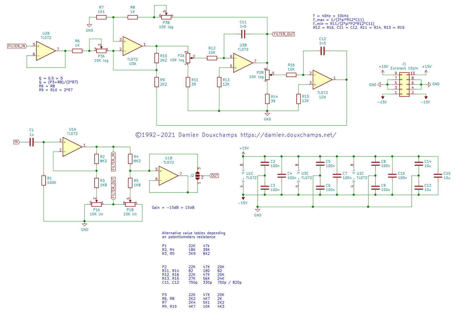
The main purpose of this article is to introduce the reader to a flexible equaliser circuit that can be used for hi-fi, mixing consoles, instrument amplifiers (especially bass guitar) or anywhere else that a simple and predictable 'parametric' equaliser is needed.
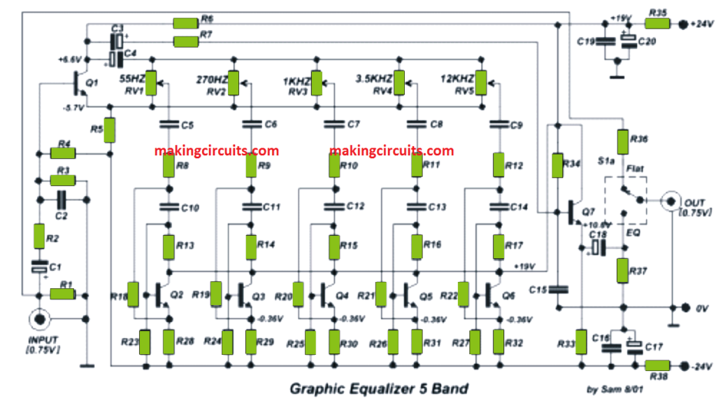
5 Band Graphic Equalizer Circuit
Most EQs for guitar are of the simple graphic variety, with tiny sliders that boost or cut specific, pre-set frequencies. These can be excellent, and are all that's needed for many players, but for guitarists who really want to get into deep, surgical tone shaping, a parametric EQ is ideal.

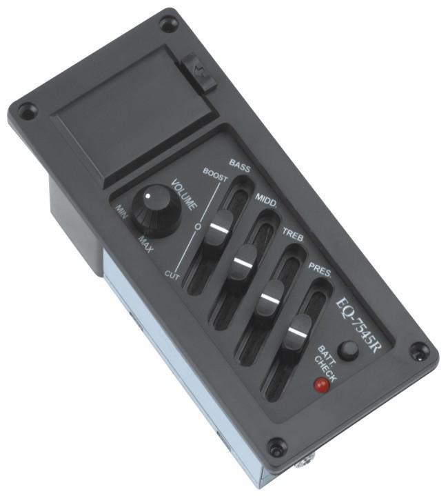
Guitar Equalizer With Volume And Tone Control Passive Control EQ 71x46MM Black, BRAND Best
A graphic equalizer is a type of complex tone control circuit which can be applied to smooth out or enhance the frequency response of any hi-fi audio amplifier, or in a guitar effects unit. To be precise, the unit can prove effective in virtually any form of audio application. The unit is quite simple to use.

10Band Equalizer CircuitsProjects
"The above schematic represents the basis for part of the classic Baxandall EQ (or rather, the passive version as the 'James' tone control - where the Baxandall began as an active circuit, i.e. it was built as a negative feedback network around a gain stage.

Modify your Boss GE7 Equalizer with upgrades! Alchemy Audio Pedal Modification Service. agh
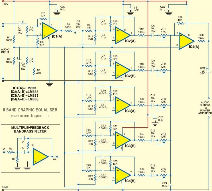
Graphic EQ Schematic Graphic EQ Parts Layout Diagram with schematic notation for the Band capacitors Graphic EQ Parts Layout Diagram, 6 band with actual capacitor values Graphic EQ Wiring Diagram, 6 Band Graphic EQ Parts Layout Diagram, 5 Band with actual capacitor values Graphic EQ Wiring Diagram, 5 Band with Gain control knob
5 Band Graphic Equaliser Circuit Scheme
The Baxandall equalizer is a shelving EQ with an extremely wide Q curve with a gentle slope. The broad curve can adjust a larger portion of the frequency spectrum, but the gentle slope gives a more natural sound and minimal phase distortion. The minimal phase distortion enables users to make bigger boosts and cuts without imparting negative.

4 Band Equalizer schematic diagram schematic Circuit diagram, Schematic design, Band
Since its rise to popularity in the mid-to-late '60s, the wah pedal's trademark sound has been used by countless guitarists across the genres of R&B, funk, fusion, rock, and heavy metal. It has become a tonal signature for guitar greats such as Frank Zappa, Jimi Hendrix, and Steve Vai. Don't be fooled by the simplicity of this pedal.
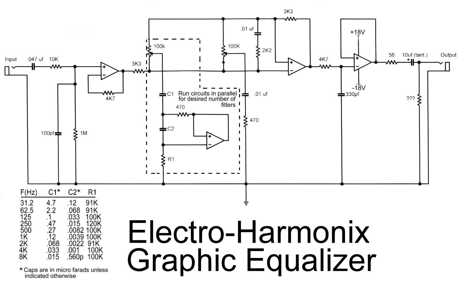
Electro Harmonix Graphic Equalizer Circuit Scheme
no, set your EQ to 0 or even turn it off, and get your amp to sound as close as you can get it what you want. once you've got it as close as possible then start messing with your EQ to perfect it.